Overview
The level of tunnelling activity in the UK is at an all time high with miles of tunnels being bored under our cities and countryside to accommodate railway lines, power cables, super sewers and conveyor systems which link deep mines to distant ports. It is an exciting time for the industry and Blakley Electrics have been busy designing and building bespoke distribution assemblies to meet the individual requirements of the different projects.
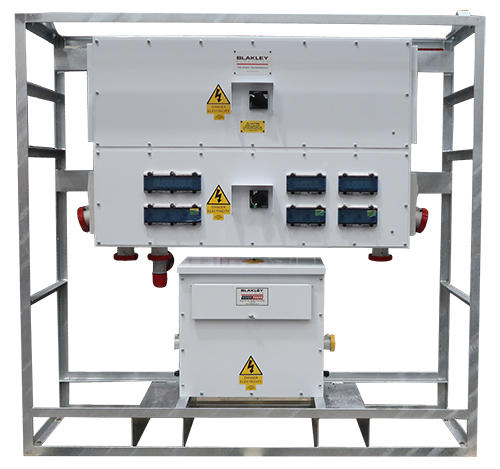
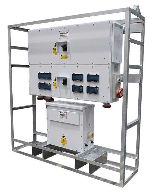
One recent requirement was for a series of free-standing, 400V tunnel distribution assemblies, which are to supply temporary Low Voltage and Reduced Low Voltage (110V) power in tunnels stretching for a total length of 6.9km (not connected as a single circuit). A wide variety of factors affect the design of a tunnel assembly and a key factor in this instance was that no temporary services can be fixed to the wall of the tunnel i.e. all assemblies have to be free-standing, which is not usually the case. To address this requirement the assembly was mounted within a heavy duty, galvanized crash frame, which not only addresses the requirement for the assembly to be free-standing but also provides the means for these substantial assemblies to be safely transported to the point of installation, which could be a distance of several miles (the crash frame incorporates fork lift pockets and an overhead lifting facility).
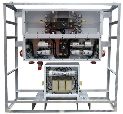
The top section of the main assembly is a cable link box fitted with a 630A 4P MCCB. The supply cable enters through one side and the distribution equipment fitted to the assembly is supplied from the live side of the MCCB. The MCCB controls the feed to the next distribution assembly and it is not connected until the next assembly in the series has been installed. This approach allows the 400V circuit to be extended as tunnelling advances.
The lower section of the main assembly incorporates 400V distribution equipment, which includes 2 no. 63A TP hard wired circuits, 2 no. 63A 5P 400V interlocked sockets and 3 no. 32A 5P 400V sockets, one of which feeds a 400:110V transformer mounted on to the base of the crash frame. The transformer is fitted with hard wired 110V lighting outlets and also 110V sockets. All outgoing ways (including RLV 110V) are individually protected by MCB and RCCB.
The tunnel lighting is fed from the RLV transformer and it is the length of the 110V lighting circuit that dictates the spacing of the Tunnel Distribution Assemblies. The typical length of a 110V lighting circuit is 100m (in-bye and out-bye from the transformer), which results in a Tunnel Distribution Assembly every 200m. On this project our i-Site lighting system is being installed, which incorporates movement detection within each luminaire. If no movement is detected, the light output drops to 20%, which reduces consumption by approximately 75% but provides a constant source of illumination. As soon as movement is detected, the light output reverts to 100%.
If you would like to discuss a requirement for tunnel distribution equipment, the Blakley Projects Team are here to help.
Project No:
SP103
Industry
Construction, Tunnelling
Category
Temporary Distribution
Year
2023
Download PDF